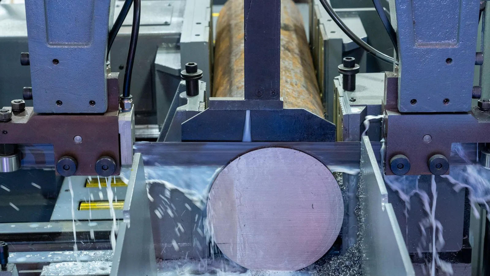
Accurate milling of extruded profiles requires proper clamping, sharp tooling, and controlled feeds. This guide covers the full process, from preparation to final measurement, ensuring dimensional accuracy and surface finish.
- Clamp extrusions to prevent vibration and deflection during milling.
- Use high-speed steel or carbide tools suited to aluminum alloys.
- Keep feeds and speeds consistent to maintain surface finish.
- Verify dimensions with calipers or CMM after machining.
- Clean chips immediately to avoid recutting and surface damage.
Why Milling Extruded Profiles Demands Care
Extruded aluminum profiles leave the die with near-final dimensions, but most engineering applications require secondary machining. Tight tolerances on mounting faces, flatness, or hole patterns rarely emerge from the extrusion process alone. Milling removes material from specific surfaces to create precise planes or features that the profile cannot achieve during extrusion.
The process demands close attention to material behavior. Aluminum extrusions commonly use alloys like 6061 or 7075, each with distinct chip formation characteristics and heat sensitivity. 6061-T6 offers good machinability and corrosion resistance, making it a default choice for structural parts. 7075-T6 provides higher strength but is more sensitive to heat and work hardening. A poor setup can cause built-up edge, work hardening, or surface tearing. The goal is to remove material cleanly while preserving the geometric integrity of the profile.
Prerequisites Before Starting
Before the first cut, several conditions must be met. Inspect the profile for die defects, burrs, or internal stress indicators. Clean the surface with a degreaser to remove mill oil or dust. Check the extrusion for warpage over its length. A warped profile will not sit flat against the machine table, leading to uneven cuts and inaccurate hole placement.
Verify the required tolerances. If the spec calls for +/- 0.05 mm flatness, the setup must support that level of precision. Standard vise jaws may not be enough for long profiles. Consider soft jaws or custom fixtures. Document the material grade and heat treatment condition. These details affect tool selection and cutting parameters. For example, 6061-T6 is softer than 7075-T6, meaning it cuts faster but requires more attention to tool wear to prevent built-up edge.
Setting Up the Workpiece
Clamping is the foundation of accurate milling. The profile must be fixed in a position that prevents rotation and lift during cutting. For short extrusions, a standard vise with aluminum or copper soft jaws works well. For longer profiles, use multiple clamping points spaced evenly along the length.
Support the profile from below where possible. Use a support table or doweled fixtures to prevent sagging. The clamping force must be firm but not so high that it distorts thin-walled sections. Check the part for movement after clamping. If it shifts, reposition the clamps. For example, a 100 mm wide extrusion might need clamps at every 200 mm interval to prevent bowing under cutting forces.
Selecting the Right Tooling
Tool selection depends on the alloy and the feature being machined. For general milling of 6061 or 7075, solid carbide end mills perform reliably. Two-flute tools clear chips efficiently and reduce heat buildup. For finishing passes, a single-flute or polished tool can improve surface finish.
Avoid dull or damaged tools. Worn edges cause chattering and poor surface quality. Inspect the tool before each job. If the flute is nicks or the edge is rounded, replace it. Carbide tools hold their edge longer than high-speed steel but require proper coolant. Aluminum is non-ferrous, so standard coolant systems work well. For instance, a 12 mm two-flute carbide end mill is suitable for roughing 6061, while a 6 mm single-flute tool is better for finishing 7075.
Defining the Machining Strategy
Plan the cut sequence. Start with roughing passes to remove the bulk of material. Use a larger depth of cut and higher feed rate. Follow with finishing passes at lower depth and finer feed. This two-stage approach controls heat and improves dimensional stability.
For flat surfaces, use a face mill or a carbide end mill in a slot cutter holder. Keep the tool axis parallel to the work surface. For drilling or tapping, center the hole using a drill guide or peck milling technique. Avoid deep cuts in one pass. Break the tool into smaller segments if the feature is large. For example, roughing a 20 mm deep pocket in 6061 might require two passes of 12 mm each, followed by a 2 mm finishing pass.
Controlling Cutting Parameters
Speed and feed rates must be balanced. Too high a speed causes heat and tool wear. Too low a speed leads to rubbing and work hardening. Adjust parameters based on the tool diameter and alloy. For aluminum, keep the chips long and flowing. If chips curl tightly, reduce the speed.
Use coolant continuously. Flood the tool and work area. Coolant also helps flush chips away from the cutting zone. Without it, heat concentrates and can alter the surface hardness. Monitor the sound of the cut. A consistent hum indicates proper engagement. A grinding or tearing sound signals a problem. For 6061-T6, typical surface speeds range from 150 to 250 m/min for carbide tools. For 7075-T6, reduce the speed by 20 to 30 percent to manage heat.
Common Mistakes to Avoid
Clamping the profile too loosely causes vibration. Even slight movement during cutting creates chatter marks and dimensional errors. Recheck clamps after each setup.
Using the wrong tool geometry for the feature leads to poor finish. A standard end mill may struggle with deep slots. Use a slotted end mill or a dedicated slotting tool instead.
Ignoring the extrusion’s surface condition. Milling over a dirty or oily surface can trap debris under the tool path. Clean the area thoroughly before machining.
Overlooking the grain direction. Extruded aluminum has a textured surface from the die. Milling across the grain can produce a rougher finish. Adjust the tool path to minimize this effect.
Final Verification and Quality Control
After machining, clean the surface completely. Remove all chips and coolant residue. Wipe the part with a lint-free cloth. Inspect the machined surfaces under good light. Look for scratches, tearing, or discoloration.
Measure the critical dimensions. Use digital calipers for general sizes. For flatness and parallelism, use a surface plate and feeler gauge or a CMM. Record the measurements against the drawing. If any dimension is out of tolerance, assess the cause. Was the clamp loose? Was the tool dull? Adjust the setup and re-machining if necessary. For example, a 0.02 mm deviation in flatness might indicate a warped fixture or an uneven clamp force.
| Feature | Recommended Tool | Typical Feed Approach |
|---|---|---|
| Flat face | Face mill or end mill | Rough then finish pass |
| Hole drilling | End mill or drill | Peck milling for depth |
| Slot cutting | Slotting end mill | Stepped depth cuts |
| Edge rounding | Ball nose end mill | Light finishing pass |
| Profile surface | End mill | Full-width pass |
Maintaining Tooling and Setup
After the job, clean the tools and store them properly. Carbide tools can be damaged by improper handling. Use tool holders that maintain runout. Check the spindle for any play or vibration. A worn spindle affects the finish quality of every subsequent part.
Keep a log of cutting parameters for each alloy and tool combination. This makes future jobs faster and more consistent. Note any changes in tool wear patterns. If a specific tool consistently fails, switch the brand or geometry. For instance, a two-flute tool might work well for 6061 but cause chatter in 7075. Testing different geometries helps identify the best match for each material.
When to Outsource Milling Services
In-house milling works best for small batches or custom features. For high-volume production, consider professional machining services. Outsourcing can provide access to higher precision equipment, specialized tooling, and quality control systems.
When evaluating a service, ask about their setup for extrusions. Do they use custom fixtures? What tolerances can they guarantee? Review samples before committing to a full order. A reliable provider will share their process and quality reports. For example, a machine shop specializing in aerospace aluminum might offer CMM verification for every batch, which is valuable for critical structural parts.
Conclusion of the Process
Accurate milling of extruded profiles is a controlled process. It relies on clean material, proper clamping, sharp tools, and precise parameters. Each step builds on the last. A defect at any stage propagates to the final part.
The verification step is not optional. It confirms the work meets the drawing. Without it, errors go undetected and cause assembly failures later. Make verification a non-negotiable part of the workflow.
Frequently asked questions
What tool is best for milling aluminum extrusions?
Solid carbide end mills are the standard choice. They hold their edge well and work efficiently with non-ferrous metals.
How should I clamp a long aluminum profile?
Use multiple clamping points spaced evenly along the length. Support the profile from below to prevent sagging and vibration.
What coolant should I use for aluminum milling?
A standard flood coolant system works well. It removes heat and flushes chips away from the cutting area.
Can I mill extrusions without a CNC machine?
Yes, manual or semi-automatic mills can be used for simple features. However, CNC offers better consistency and repeatability.
How do I check flatness after milling?
Place the part on a surface plate and use a feeler gauge. A CMM provides more detailed measurements for complex geometries.