Buyers and engineers need a structured audit to verify profile dimensions, wall thickness, and fabrication compatibility. This checklist covers design checks across geometry, material, and downstream processing to prevent defects and rework.
- Verify wall thickness against minimum extrusion limits before releasing drawings.
- Check downstream fabrication requirements such as machining, welding, and assembly clearances.
- Review flat and twisted tolerances to ensure the profile fits into its intended application.
- Confirm material grade and heat treatment match the mechanical demands of the application.
Pre-Release Drawing Checks
Before sending a profile to an extrusion mill, run the design through a structured audit. The goal is to catch errors while the cost to fix them is still low. A profile that fails basic geometry checks often arrives at the factory with rework costs that exceed the value of the part.
Start with the cross section. Confirm that every wall thickness meets the minimum limit for the alloy and the extrusion speed expected. Thin walls deform during cooling. If the design has a wall below the mill’s practical minimum, the profile will likely warp or collapse. Check the corner radii as well. Sharp internal corners trap stress. They also create thin spots that are prone to cracking during machining or heat treatment.
Review the overall depth and width. A profile that is too deep for the mill’s press size may require a different die design or multiple extrusions. Confirm that the cross section is balanced. Asymmetric shapes often twist during cooling. A symmetric design around the neutral axis reduces this risk.
Wall Thickness Validation
Wall thickness is the most common source of extrusion failure. Thin walls cool faster than thick ones. This temperature difference causes uneven contraction. The result is bowing or twisting in the final bar.
Use the following minimum values as a starting point for standard aluminum alloys. These are general limits, not absolute rules. The mill’s specific capabilities and the alloy’s behavior will determine the true lower bound.
| Feature | General Minimum Wall Thickness | Risk if Too Thin |
|---|---|---|
| Structural Load Bearing | 2.0 mm | Insufficient bending strength |
| Thin Ribs | 1.5 mm | Bowing and collapse |
| Thin Flanges | 1.2 mm | Twisting and warping |
| Thin Walls in Hollow Sections | 1.0 mm | Wall distortion |
| Thin Walls in Solid Sections | 0.8 mm | Surface pitting |
Do not design for the absolute minimum unless the application demands it. Add a margin for machining. If the profile will be machined, the final dimension must be larger than the machined size. Subtract the tool diameter and the required clearance. If the wall is too thin to allow this subtraction, the design will not work.
Check the ratio between the maximum and minimum wall thickness. A large difference increases the risk of distortion. Keep the ratio as low as practical. If a design requires a thick web and thin flanges, consider adding ribs to distribute the material more evenly.
Downstream Fabrication Compatibility
Design the profile for how it will be used after extrusion. A profile that is easy to extrude but hard to fabricate is a poor design.
Check the machining requirements. Identify every surface that will be machined. Ensure the extruded dimension is larger than the final machined dimension. Include a tolerance for the tool. If the profile will be milled, drill, or tapped, verify that the wall is thick enough to hold the tool without breaking through.
Review the fastening points. If the profile will be bolted, the hole diameter must be larger than the bolt. Add clearance for the washer and the bolt head. Check the hole position. Holes too close to the edge reduce the local strength. Keep a minimum distance from the edge. This distance is typically related to the hole diameter and the wall thickness.
Check the welding requirements. If the profile will be welded, the design must allow for heat input. Thin walls near a weld zone will soften. They may warp or burn through. Avoid thin walls in areas that will be welded. If welding is required, increase the wall thickness in that zone.
Review the assembly clearances. If the profile will be joined to other parts, the dimensions must fit. Check the tolerances. Aluminum extrusions have larger tolerances than machined parts. Design the assembly to accommodate this. Add gaps for thermal expansion. Aluminum expands more than steel. A tight fit at room temperature may become a jam at operating temperature.
Geometric and Dimensional Checks
Review the cross section for symmetry. A symmetric profile is easier to extrude and less likely to twist. Check the shape for balanced material distribution. If one side is significantly heavier than the other, the profile will tend to bow during cooling.
Check the corner radii. Internal corners should be rounded. External corners can be sharper, but they are prone to breakage. Add a small radius to external corners to protect them during handling.
Review the flatness and twist tolerances. Standard extrusions have specific limits for flatness and twist. These limits depend on the profile size and the alloy. If the application requires high precision, standard tolerances may not be enough. Specify tighter tolerances in the drawing. Be aware that tighter tolerances increase the cost.
Check the overall length. Long profiles are harder to handle. They are also more prone to bending during transport and storage. If the profile will be cut to length, specify the cut length and the tolerance. If the profile will be used as a long continuous part, consider the bending radius. Aluminum extrusions can bend, but they have a minimum bending radius. Bending below this radius causes cracking.
Material and Surface Finish
Select the alloy based on the mechanical requirements. Different alloys have different strengths, corrosion resistance, and machinability. Choose the alloy that matches the application. Do not select a high-strength alloy if a standard alloy will do. It will increase the cost without adding value.
Check the heat treatment. Extruded profiles are usually supplied in a specific temper. The temper determines the mechanical properties. A T6 profile is stronger than an O profile. Select the temper based on the required strength. If the profile will be machined, a softer temper is easier to machine. If the profile will be welded, a specific temper may be required to avoid cracking.
Review the surface finish. The finish affects the appearance and the corrosion resistance. A bare surface is cheaper but corrodes faster. A painted or anodized surface is more expensive but more durable. Check the finish for the application. If the profile will be used outdoors, a protective finish is required. If the profile will be machined, the finish must allow for the machining process.
Check the coating thickness. If the profile will be anodized, the coating adds to the wall thickness. This reduces the effective wall thickness. Account for this in the design. If the wall is thin, the coating may make it too thin.
Final Audit Before Release
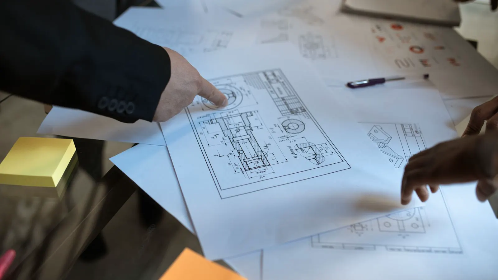
Run the profile through a final audit before releasing the drawing. Check every dimension, every tolerance, and every note. Verify that the drawing is clear and unambiguous. Use standard symbols and units. Avoid free-form text where a standard symbol will do.
Review the material specification. Confirm the alloy, the temper, and the surface finish. Check the tolerance class. Verify the length and the cut tolerance.
Check the downstream fabrication notes. Confirm that the machined surfaces, the fastening points, and the welding zones are clearly marked. Review the assembly requirements. Check the tolerances for the mating parts.
Send the drawing to the extrusion mill for a feasibility review. The mill will check the design against their capabilities. They may suggest changes to improve the extrusion. Review their feedback carefully. Some changes are minor. Others may require a redesign.
This checklist is a starting point. Adjust it for your specific application. Add checks for your industry. For example, a profile for a solar rack may require checks for UV resistance and thermal expansion. A profile for a machine frame may require checks for vibration and fatigue.
Common Design Mistakes to Avoid
Avoid designing for the absolute minimum wall thickness. It saves material but increases the risk of failure. Add a margin for safety and fabrication.
Avoid ignoring the downstream fabrication. A profile that is easy to extrude but hard to machine is a poor design. Design for the entire process, not just the extrusion.
Avoid using standard tolerances for high-precision applications. If the application requires high precision, specify tighter tolerances. Be aware that tighter tolerances increase the cost.
Avoid selecting a material that is too strong. A high-strength alloy is harder to machine and more expensive. Use a standard alloy if it meets the requirements.
Avoid ignoring the surface finish. A bare surface corrodes faster. Select a finish that matches the environment. Check the coating thickness. It reduces the effective wall thickness.
These mistakes are common. They are also easy to fix. Run the design through this checklist before releasing it. Catch the errors early. Save time and money.
Frequently asked questions
What is the minimum wall thickness for an aluminum extrusion?
The minimum wall thickness depends on the alloy, the extrusion speed, and the profile shape. General minimums range from 0.8 mm for thin solid walls to 2.0 mm for load-bearing walls. Always verify with the extrusion mill.
How do I check if a profile will twist during extrusion?
Check the cross section for symmetry. An asymmetric shape is more likely to twist. A balanced design around the neutral axis reduces the risk. The mill can also provide a feasibility review based on the die design.
What tolerance should I use for machined surfaces on an extrusion?
Standard extrusion tolerances are larger than machined tolerances. Specify the extruded dimension and the machined dimension separately. Add a tolerance for the tool. The final machined dimension must be smaller than the extruded dimension.
Can I weld a thin-walled aluminum extrusion?
Welding thin-walled aluminum is difficult. The heat input can soften the wall or cause burn-through. Increase the wall thickness in the weld zone. Avoid thin walls in areas that will be welded.
How does the surface finish affect the wall thickness?
A coating such as anodization or paint adds to the wall thickness. This reduces the effective wall thickness. Account for the coating thickness in the design. If the wall is thin, the coating may make it too thin.