A profile cross section is the two-dimensional slice of an extrusion. It defines the shape, wall thickness, and internal features that determine structural strength, weight, and material cost. Understanding this view is the first step in evaluating any extruded aluminum product.
- The cross section is the blueprint for the profile's geometry, including walls, ribs, and cavities.
- Shape choices balance stiffness, weight, and material use, directly impacting cost and application fit.
- Designers must consider manufacturing limits, such as die size and cooling, when finalizing a cross section.
- Sourcing requires matching the cross section to available profiles or custom die costs.
What Does the Term Cross Section Actually Mean
The profile cross section is the view you see when you slice the extruded aluminum bar perpendicular to its length. Imagine taking a long square bar and cutting it with a saw. The flat face exposed by the cut is the cross section.
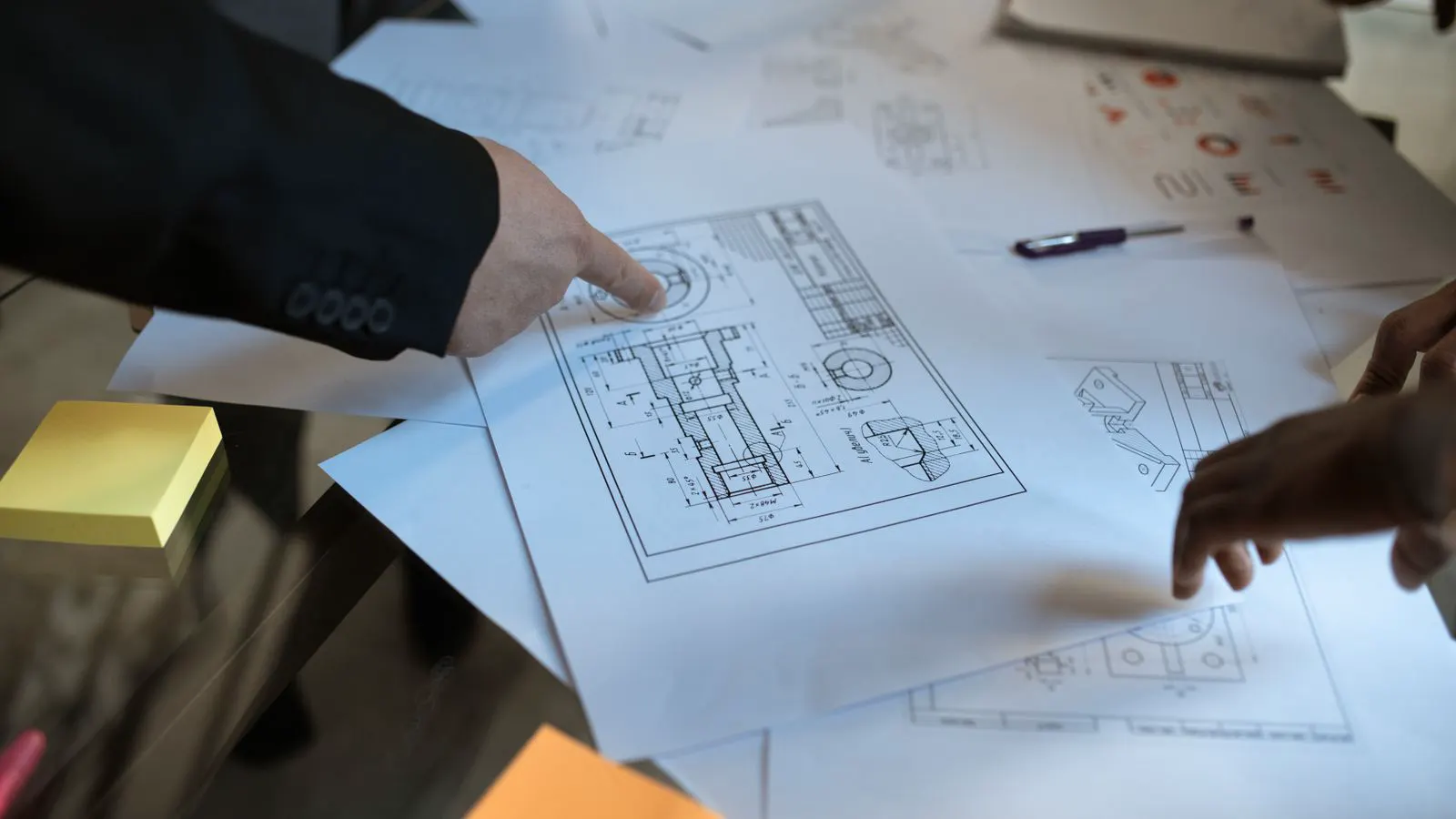
This two-dimensional drawing is the most important reference for extrusion buyers and engineers. It shows every wall, rib, flange, and cavity. The shape in that slice repeats along the entire length of the profile.
A standard square tube, for example, has a simple cross section with four walls and a hollow center. A more complex profile might have a central flange with multiple fins on each side. The complexity of that slice dictates the die design, the cooling time, and the final performance.
Why the Cross Section Drives Design Decisions
Every feature in the cross section has a function. A thicker wall adds stiffness but consumes more aluminum. A rib or fin increases the bending resistance of a long member without adding heavy solid mass. A cavity or pocket reduces weight and material cost while keeping the outer shape intact.
Designers balance these factors based on the application. A window frame needs a specific cross section to hold glass securely and manage thermal expansion. A heat sink requires a cross section with many thin fins to maximize surface area. A structural beam for a building frame relies on a shape that resists bending loads efficiently.
The choice of shape also affects the manufacturing process. A cross section with deep pockets or sharp internal corners is harder to extrude. The molten aluminum must flow smoothly through the die. If the design is too aggressive, the material may not fill the die properly, leading to defects. Engineers work with extruders to adjust the geometry so it can be produced reliably.
How Shape Affects Strength and Weight
The relationship between shape and performance is central to extrusion profile design. A solid bar and a hollow profile of the same outer dimensions will have very different weights and stiffness properties. The hollow shape removes material from the center, where bending stress is lowest. This creates a strong, lightweight member.
Consider a rectangular tube. If you make the walls very thin, the profile is light but may buckle under pressure. If you make them thick, it is stiff but heavy. A practical solution often involves adding internal ribs. These ribs act like tiny struts inside the cavity, increasing the bending resistance without significantly increasing the wall thickness.
This is why the cross section is so critical for sourcing. If you ask a supplier for a specific shape, they need to know if the required stiffness can be achieved with the available material thickness. They also need to check if the shape can be produced with standard die sizes or if a custom die is required.
Key Features in a Typical Extrusion Cross Section
Most extrusion profiles share a set of common geometric features. Understanding these terms helps in reading technical drawings and communicating with suppliers.
| Feature | Description | Common Use |
|---|---|---|
| Wall | The main outer or inner boundary of the profile | Structural support, mounting |
| Flange | A flat, extended surface around the perimeter | Fastening, alignment, thermal expansion |
| Rib | A thin, protruding internal or external support | Increased stiffness, heat dissipation |
| Cavity | An enclosed space within the profile | Weight reduction, cable management |
| Corner | The intersection of two or more walls | Structural integrity, stress concentration |
The flange is often overlooked but is critical for assembly. It provides a flat surface for bolts or screws. The rib is a tool for efficiency. A small rib can add significant bending stiffness. The cavity is a tool for economy. It removes material from areas that do not need it.
How Cross Section Design Affects Sourcing
When you specify a profile, you are essentially specifying a cross section. This shape determines the cost and lead time. If the shape is a standard industry profile, it may be in stock or produced on a regular schedule. If it is a custom shape, the supplier must design and machine a new die.
Die design is a significant cost and time factor. A complex cross section with many internal details requires a more expensive die and longer production cycles. It may also require more careful temperature control in the extrusion line.
For many buyers, the strategy is to look for a standard profile that is close to the desired shape and then modify it if necessary. For example, if a standard I-beam profile is close to the required structural shape, it might be cut and welded to create the final assembly. This can be cheaper and faster than commissioning a custom extrusion.
However, for applications where weight or specific surface features are critical, a custom cross section is often necessary. The key is to define the cross section clearly from the start. Include wall thicknesses, corner radii, and any tolerances on the drawing. This reduces the risk of miscommunication and rework.
Practical Example: Designing a Simple Frame Profile
Imagine you are designing a lightweight frame for a machine guard. The frame must resist bending loads from the machinery but keep the overall weight low.
A solid rectangular bar would be simple but heavy. A hollow rectangular tube is lighter. To improve stiffness without adding weight, you could add a central web inside the tube. This web divides the hollow space into two smaller cavities.
This change to the cross section increases the bending resistance. The web acts as a rib, supporting the side walls. The material is used more efficiently. The profile is still lighter than a solid bar, but it is stiffer than a simple tube.
When you present this cross section to a supplier, they can evaluate it. They will check if the web is thick enough to extrude without defects. They will check if the corners are rounded enough to allow material flow. They will then quote the die cost and the profile cost.
This example shows how the cross section is not just a drawing. It is a functional tool. It determines how the part behaves and how it is made.
Common Mistakes in Profile Design
New designers often make a few common errors when working with extrusion cross sections. One mistake is designing sharp internal corners. Molten aluminum does not flow well into sharp corners. The material may stop short, leaving a void. Rounding the internal corners with a small radius solves this problem.
Another mistake is making the wall thickness too thin. While thin walls save material, they can be difficult to extrude and may not provide enough stiffness. The aluminum must cool and solidify as it passes through the die. If the wall is too thin, it may deform or crack before it is fully solid.
A third mistake is ignoring the cooling time. Complex shapes with many fins or deep pockets take longer to cool. This slows down the production line. If the profile is too complex, the cost per meter increases. Designers must balance the desired shape with the practical limits of the extrusion process.
Conclusion
The profile cross section is the foundation of extrusion design. It defines the shape, the material use, and the structural performance. Understanding the features of a cross section, such as walls, flanges, and ribs, allows you to make informed sourcing decisions.
A clear cross section drawing is the most important document when working with an extruder. It communicates the design intent and reduces the risk of errors. As you evaluate potential profiles, focus on how the shape affects strength, weight, and cost.
By paying attention to these details, you can select a profile that meets the technical requirements while remaining practical to manufacture. The cross section is where design meets production. It is the key to a successful extrusion project.
Frequently asked questions
Can I change the cross section of an existing extrusion?
No, the cross section is fixed during the extrusion process. To change the shape, you must commission a new die. Post-extrusion machining can adjust surface features, but it cannot change the fundamental geometry.
What is the difference between a standard and custom cross section?
A standard cross section is a shape already produced by the extruder with an existing die. A custom cross section is a new shape that requires the design and machining of a new die, which adds cost and lead time.
How does the cross section affect the weight of the profile?
The volume of material in the cross section directly determines the weight per meter. A shape with more solid material and fewer cavities will be heavier. A shape with larger cavities and thinner walls will be lighter.
Are there limits to how complex a cross section can be?
Yes, there are practical limits. The die size, the cooling capacity of the extrusion line, and the flow properties of the aluminum alloy all influence the maximum complexity. Deep pockets and sharp corners are particularly difficult to produce.
How do I specify the cross section to a supplier?
Provide a detailed 2D drawing of the cross section. Include all dimensions, wall thicknesses, corner radii, and surface finish requirements. Specify the alloy and tolerance classes to ensure accuracy.